Steel Connection Design for Oil & Gas Structures | KHAAS
Steel connections transfer forces between beams, columns, braces and supports in oil and gas plant structures. Their behavior must match the assumptions used in the structural analysis while allowing practical fabrication, inspection and site assembly.
KHAAS Design & Engineering provides bolted and welded connection design support for pipe racks, equipment platforms, skid frames and industrial steelwork. This guide explains the inputs, methodology and detailing checks that shape a coordinated connection design.
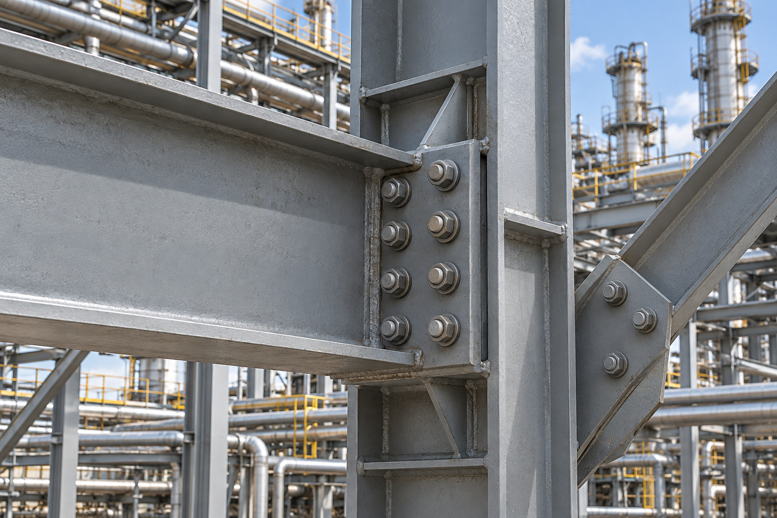
Why connection behavior matters
A connection carries combinations of shear, axial force and bending moment. Its stiffness and capacity influence how the structure distributes load. A joint detailed as flexible should not be assumed to provide rigid restraint without justification.
In oil and gas facilities, piping reactions, equipment loads, wind, seismic actions and thermal effects can create different governing combinations. Connection design should use the relevant signed forces and combinations from the structural model.
Steel connection design methodology
Review member sizes, material grades, connection forces and structural model assumptions.
Select a suitable joint arrangement with the required strength and stiffness.
Assess bolts, welds, plates and connected members for the applicable limit states.
Check eccentricity, prying effects and local member behavior where relevant.
Coordinate bolt access, weld access, tolerances and erection sequence.
Issue calculations and connection details consistent with the adopted project code.
Complex geometries may need a detailed local analysis. The model should still reflect the intended force transfer and boundary conditions.
Connection types used in oil and gas steelwork
Shear connections: beam end joints designed for the required forces and rotation behavior.
Moment connections: joints that transfer bending together with associated shear and axial forces.
Bracing connections: gusset and brace joints forming the lateral load path.
Splices: member joints coordinated with fabrication lengths and transport limits.
Base plates and anchors: interfaces transferring steelwork reactions to the supporting concrete.
Connection selection depends on the structural system and installation requirements, not only the magnitude of a single force.
Fabrication, inspection and interface checks
Detail weld lengths, bolt grades, hole requirements and plate dimensions clearly. Allow space for tightening tools and inspection, and coordinate coatings, fire protection and site access with the project team.
Typical deliverables include connection calculations, marked-up connection schedules and fabrication details within the agreed scope. Changes to member sizes or force envelopes should trigger a review of affected joints.
Related topics include plant foundation design and modular skid engineering.
Steel connection design FAQs
Are bolted joints better than welded joints?
Neither is universally preferable. The choice depends on force transfer, fabrication conditions, site access, inspection requirements and the erection sequence.
Can standard connection details be reused?
Only after checking the actual geometry, forces, materials and project requirements against the detail’s design assumptions.
What inputs are needed?
Provide structural drawings, member sizes and grades, signed connection forces with load combinations, adopted codes, bolt and weld specifications and fabrication preferences.
Request connection design support
Send your oil and gas steelwork drawings and connection requirements to KHAAS Design & Engineering for review.
Phone: +91 95511 44115
Email: inquiries@khaas-group.com